Your are here:Home > Products > Air Conditional Relay > G7L Relay
>> Category:Air Conditional Relay
>> E-mail:aultop@aultop.com.cn
>> Tel:+86-577-62777339
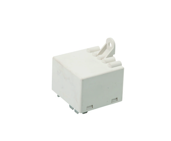
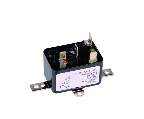
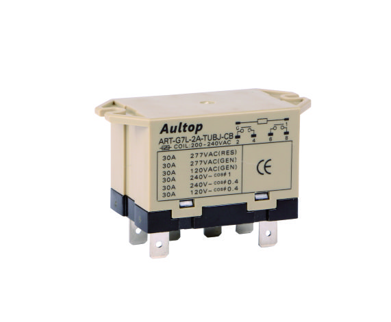
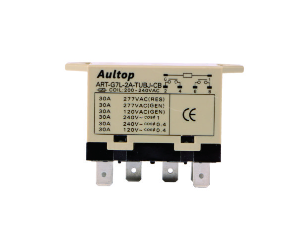
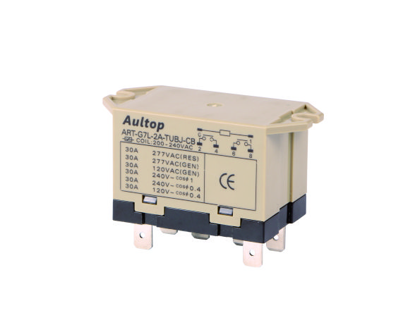
1) A High-capacity, High-dielectric-strength relay,Compatible
with Momentary Vlotage Drops
2) Wide-range AC-activated coil that handles 100 to 120 or 200
to 240VAC at either 50 or 60Hz.
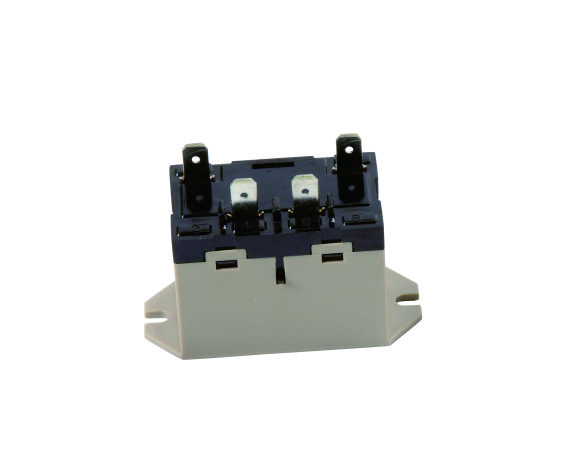
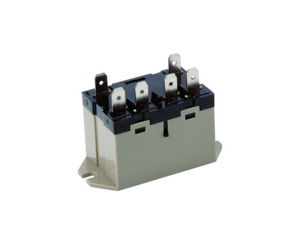
3) 250# quick connect termination
4) Miniatre size for maximum switching power,particularly for
inductive loads
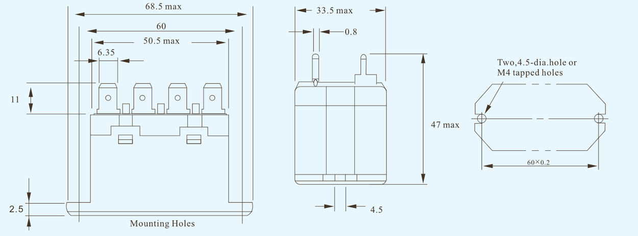
Ordering Information
|
Aultop Relay |
Type |
Number Of Poles |
Contact Form |
Terminal Shap |
Mounting Construction |
Special Functions |
|
ATR |
G7L |
1 |
A |
T |
UB |
J |
|
|
|
1: 1POLE 2: 2POLE |
SPST-NO DPST-NO |
Quick connect terminals(250#) |
Upper bracket |
with test button |
|
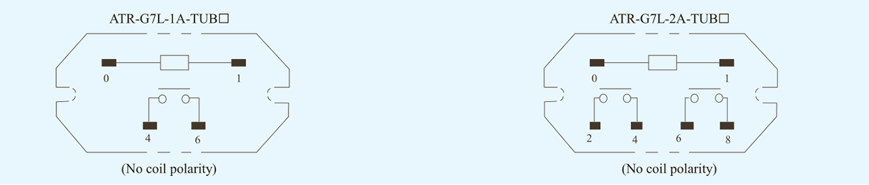
Contact Form |
ATR-G7L-1A-TUB□ |
ATR-G7L-2A-TUB□ |
||
|
|
Load Resistive load |
Inductive load (Cos∮=0.4) |
Resistive load |
Inductive load |
|
Item |
Double Break |
|||
|
Contact Type Contact Material Rated Load |
Ag Alloy |
|||
|
30A at 220VAC |
25A at 220VAC |
25A at 220VAC |
||
|
30A |
25A |
|||
|
Rated Carry Current |
250VAC |
|||
|
Max. Switching Current |
30A |
25A |
||
Characteristics
|
Weight: |
Approx.90g |
|
Termination: |
QC |
|
Construction: |
Dust protected |
|
Ambient Operationg Temperature |
-25℃ to 60℃ (with no icing or condensation) |
Coil Ratings
|
Item |
Raated Current (ma) |
Coil Resistance (Ω) |
Coil Inductance (h) |
Must Operate Voltage |
Must Release Voltage |
Max. Permissible Voltage |
Power Consumption (va-w) |
|
|
Rated Voltage |
Armature ON |
Armature OFF |
On The Bases Of Rated Voltage |
|||||
|
12VAC |
142 |
|
|
|
75%Max |
15% Min. |
110% |
Approx. 1.7to 2.5 |
|
24VAC |
71 |
|||||||
|
50VAC |
34 |
|||||||
|
100-120VAC |
17.0 to 20.4 |
75V Max. |
18V Min. |
132V |
||||
|
200-240VAC |
8.5 to 10.2 |
150V Max. |
36V Min. |
264V |
||||
|
6VDC |
317 |
18.9 |
0.09 |
0.21 |
75% Max |
15% Min. |
110% |
Approx. 1.9 |
|
12VDC |
158 |
75 |
0.37 |
0.88 |
||||
|
24VDC |
79 |
303 |
1.42 |
3.54 |
||||
|
48VDC |
40 |
1220 |
6.1 |
15.3 |
||||
|
100VDC |
19 |
5260 |
21.3 |
60.0 |
||||
|
Contact Resistance *1 |
50 mΩ Max. |
|
|
Operate Time *2 |
30 ms Max |
|
|
Release Time *3 |
30 ms Max |
|
|
Max. Operating Frequency |
Michanical |
1,800 operations/hr |
|
Rated Load |
1,800 operations/hr |
|
|
Insulation Resistance *3 |
1,000 MΩ min |
|
|
Dielectric Strength |
Between Coil And Contacts |
4,000 VAC min. 50/60Hz for 1 min |
|
Between Contacts Of Same Polarity Coil And Contacts |
2,000VAC, 50/60Hz for 1 min |
|
|
Between Contacts Of Different Polarity (dpst-no Model) |
||
|
Impulse Withstand Voltage |
1,000V between coil and contact *4 |
|
|
Vibration Resistance |
Destruction |
10 to 55 to 10 Hz, 0.75 mm single amplitude (1.5mm double amplitude) |
|
Malfunction |
10 to 55 to 10 Hz, 0.75 mm single amplitude (1.5mm double amplitude) |
|
|
Shock Resistance |
Destruction |
1,000 m/s2 |
|
Malfunction |
100 m/s2 |
|
|
Dndurance |
Mechanical |
1,000,000 operations min. ( at 1,800 operations/hr) |
|
Electrical *5 |
1,000,000 operations min. ( at 1,800 operations/hr under rated load) |
|
|
Failure Rate (p Level) (reference Value *6) |
100mA at 5VDC |
|