Your are here:Home > Products > Digital Electric Power Meter > Digital Voltage Meter
>> Category:Digital Electric Power Meter
>> E-mail:[email protected]
>> Tel:+86-577-62777339
Intelligent digital voltage meter display are used in electrical power grid and automation ,
control system to measure voltage parameter ,according to the additional function devision ,
we have X,K Two series digital meter .
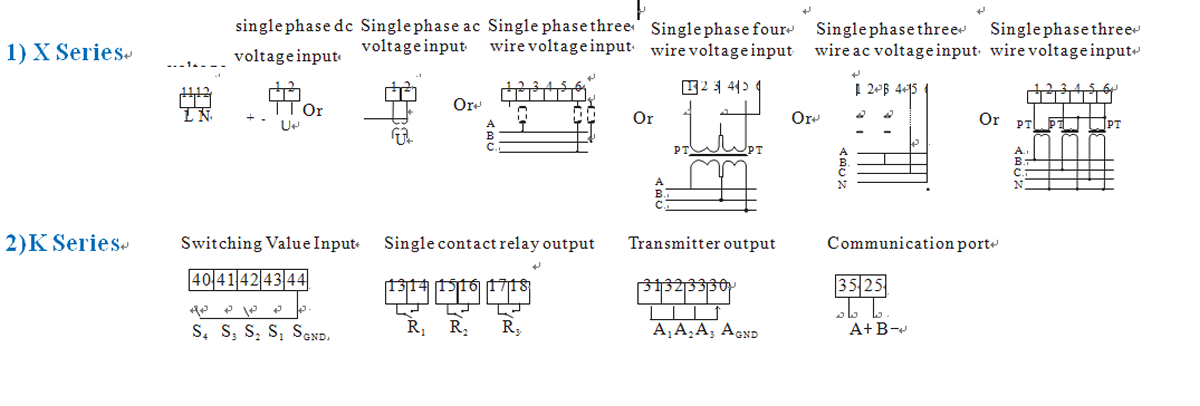
X Series digital voltage meter via directly AC/DC 0-20mA ,4-20mA,0-75mV Sampling ,
adopts ture RMS measure voltage, and with digital (LED) directly display figure electric meter.
K series digital meter are based on the X-series add one to four channels open input Sn(n=1-4)
realize "remote control ", one to three relay alarm output Rn(n=1~3) realize "remote control" ,
and one to three analog transmit output An(n=1~3)to 4-20 mA ,with RS485 digital interface, adopts
Modbus-RTU protocol,realize "remote control"function .
From the measurement of power network can devided into single phase (ac/dc) current meter
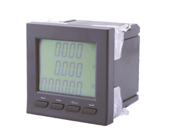
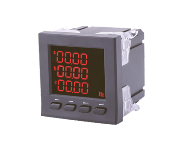
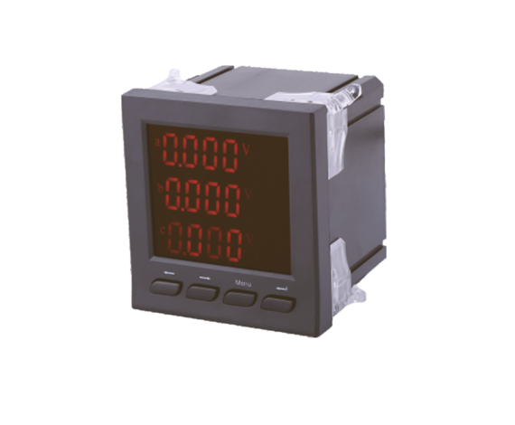
and three phase current meter .Single phase voltage meter with single row (LED )or LCD dislay
way ,three phase voltage meter with three rows digital (LED ) or LCD dislay.
Please reference to the technical Indexon the meter
Product Select Table
|
Product Model |
Phase |
□ Input Way |
■ Outline code (Code please refer to outline dimensions drawing) |
Communication |
Value Switching |
Output Relay |
Output Analog |
Dispaly |
|||||||||
|
4 AC |
5 DC |
1 |
2 |
3 |
4 |
5 |
9 |
A |
D |
LED |
LCD |
||||||
|
ADM□ I- ■ X1 |
S |
√ |
√ |
√ |
√ |
√ |
— |
√ |
√ |
√ |
√ |
— |
— |
— |
— |
√ |
— |
|
ADM□ I- ■ K1 SnRAC |
S |
√ |
√ |
— |
√ |
√ |
— |
— |
√ |
√ |
— |
√ |
1~4 |
√ |
√ |
√ |
— |
|
ADM□ I- ■ KY1 SnRAC |
S |
√ |
√ |
— |
√ |
√ |
— |
— |
√ |
√ |
— |
√ |
1~4 |
√ |
√ |
— |
√ |
|
ADM□ I- ■ X4 |
T |
√ |
— |
— |
√ |
√ |
— |
— |
√ |
√ |
√ |
— |
— |
— |
— |
√ |
— |
|
ADM□ I- ■ K4 SnRnAnC |
T |
√ |
— |
— |
√ |
√ |
— |
— |
√ |
注① |
注② |
√ |
1~4 |
1~3 |
1~3 |
√ |
— |
|
ADM□ I- ■ KY3 SnRnAnC |
T |
√ |
— |
— |
√ |
√ |
— |
— |
√ |
注① |
注② |
√ |
1~4 |
1~3 |
1~3 |
— |
√ |
Technical Index
|
|
Indicator |
|
|
Class of Precision |
Current ,Voltage ,active energy :0.5 reactive energy 1, frequency :±0.1 |
|
|
Display |
LED OR LCD |
|
|
Input |
Nominal Input |
VoltageAC100V、400Vetc.;Current AC1A、5A etc. |
|
OverLoad |
Voltge/Current continued:1.2time,Instantaneous:2 time |
|
|
Frequency |
40 ~ 65Hz |
|
|
Power |
Working Range |
AC220V;AC/DC85 ~ 270V |
|
Power consumption |
< 5A |
|
|
Transmitting Output |
DC4-20mAwhen current output load < 510Ω,DCO-5Vwhen voltage output load > 20KΩ |
|
|
Communication Port |
RS-485port,Modbus-RTUprotocol ,Baud rate 9600select 2400,4800)bps |
|
|
Relay Output |
relay output,relay contact capacity:AC5A/250V impedance,DC5A/30 impedance |
|
|
Switching Value input |
Switching input,stem node piont ,R < 500Ω on;R > 100KΩ off |
|
|
Isolation resistance |
power and input > AC2KV,power and output > AC2kV,Output and Input > AC1KV |
|
|
Insulation resistance |
≥ 100MΩ |
|
|
Average no fault working time |
≥ 5000h |
|
|
Working Condition |
Ambient Temperature :-10-55℃,Relative Humidity ≤ 93%,no aggressive gas |
|
|
Save Environment |
-20-75℃,relative humidity ≤ 93% |
|
|
Altitude |
≤ 2500m |
|
Outline Dimension Table
|
Outline Code |
Frame Dimension (mm 2) |
Loading Screen With Dimension (mm 2) |
Cutout Dimension (mm 2) |
Installation depth (mm ) (not including frame thickness) |
|
1 |
160×80 |
151×75 |
152×76 |
76 |
|
2 |
120×120 |
110×110 |
111×111 108×108 |
55.5Series /2 M /2K4) |
|
93.5(Other) |
||||
|
3 |
80×80 |
75×75 |
76×76 |
75 |
|
4 |
120×60 |
115×55 |
116×56 |
93 |
|
5 |
96×48 |
90×43 |
91×44 |
117 |
|
9 |
96×96 |
90×90 |
91×91 88×88 |
75 |
|
A |
72×72 |
66×66 |
67×67 |
75 |
|
D |
48×48 |
44.5×44.5 |
45×45 |
89 |